
This article summarizes Chapter 5. Superscalar Techniques of Modern Processor Design, Shen, P. S. and Lipasti, M. H.
Processing a program can be thought of as involving three components of flows:
- Instruction flow
- Register data flow
- Memory data flow
Each flow is roughly associated with each of the three kinds of instructions: branch, ALU, and load/store. This chapter goes through the techniques utilized in superscalar processor design, classified based on their association with the three kinds of flows.
1. Instruction Flow Techniques
Instruction flow is related to the first two stages of the pipeline: fetch and decode. In the traditional — maybe obsolete — perspective which divides the processor into control path and data path, the instruction flow clearly corresponds to the control path. The primary goal of it is to maximize the supply the instructions to the pipeline.
The maximum throughput of a pipeline is achieved when it is in the streaming mode, that is, when there is no branch that disrupts the execution. Branching causes unnecessary stalls, and a cycle of stall is equivalent to the number of nops equal to the pipeline width. Therefore, even a few cycles of stall can cause a significant performance degradation.
In the case of conditional branches, the count of stalled cycles is dictated by:
- the target address generation and
- condition resolution.
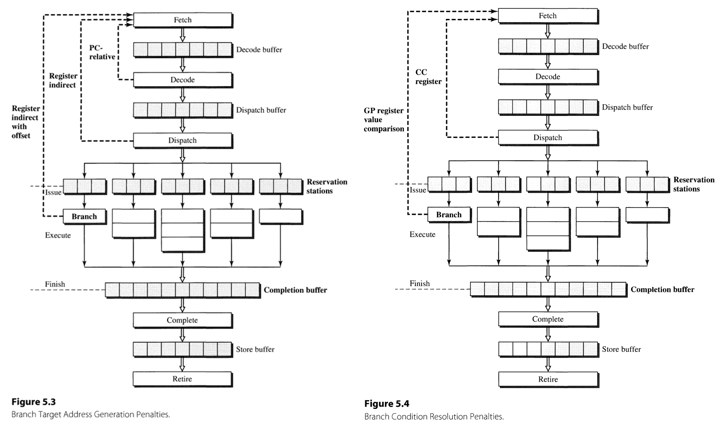
For example, the branching target in case of PC-relative addressing is determined at the decoding stage, whereas in register indirect without and with offset it is at the dispatch and execution stage (Figure 5.3).
Also, condition resolution using condition codes is finished at the dispatch stage, whereas that using general-purpose registers is finished at branch functional unit. The number of stalled cycles is determined as the maximum of stalls that is required by the target address generation and condition resolution.
Branch Prediction Techniques
There are two key techniques within branch prediction: (1) branch target speculation and (2) branch condition speculation.
The branch target speculation uses branch target buffer(BTB), which is a buffer that stores the pairs of (address of branch instruction(BIA), the target of that branch(BTA)), associatively accessed by BIA. When hit occurs to the BTB, the BTA is accessed from the table and is used as the next fetch address. Nonspeculative execution that is held several cycles later is used to validate the actual branch target and is used to update the BTB.
The branch condition speculation is implemented in multiple ways with ranging complexities, including:
- Predict not taken is the simplest way to perform this.
- Inserting a branch hint bit can be performed to the instruction encoding, with a little modification to the ISA.
- The method using target address offset is a simple though effective way, triggering the branch only if the target address is smaller than the current instruction’s address.
The technique most commonly employed in modern processors leverages the branch execution history. The method employs two bits per entry to store the state of an FSM, which can be accessed by the subset of branch instruction address. In many cases, the FSM is designed so that two consecutive misses lead to the change of its prediction (2-bit saturating counter). The method can also be jointly implemented with the branch target predictors, by augmenting BTB with a history field.
Branch Misprediction Recovery
The recovering logic must be implemented for the cases where the branch speculation turns out to be wrong. This is done by tagging the instructions that are the results of a speculative branching with the same speculation tag. When speculating, addresses of all the predicted branches are buffered in some storage.
Once a misprediction is detected, the speculation tags are used to identify the instructions that must be eliminated from the decode stage, dispatch buffer, and reservation station.
Advanced Branch Prediction Techniques
The dynamic branch prediction still has limitations, as it makes predictions based on a limited history of the branch without considering the context. Yeh and Pratt coped with this problem by suggesting a two-level adaptive branch prediction technique.
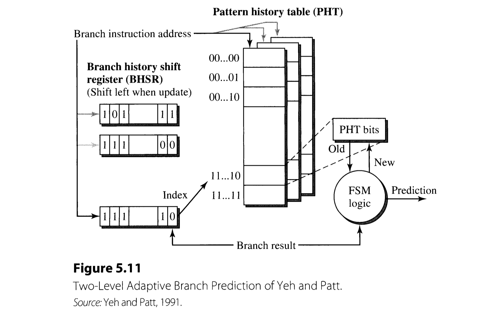
The Yeh-Pratt branch prediction algorithm employs two kinds of memory devices: branch history shift register(BHSR) and pattern history table(PHT). BHSR records the history of the recent $k$ branch results, which is used for indexing within the PHT. The resulting PHT entry encodes the state of branch prediction FSM.
Here, BHSR can be implemented in two different manners:
- Global(G), in which only one BHSR aggregatively saves the results of all branches in the program.
- Individual(P), a. k. a. per-branch, which employs a set of BHSRs that can be accessed based on the branch instruction address(as in Figure 5.11).
There are also three options for PHT implementation:
- global(g), which incorporates only one PHT that is used globally regardless of the instruction.
- individual(p), that employs the set of PHTs each of which are dedicated for the individual branch instruction.
- shared(s), in which each PHT corresponds to a subset of instructions.
In addition, the scheme is called whether adaptive(A) or not ,depending on the use of history-based FSM. For example, a GAg implementation uses a global BHSR, a global PHT, and the prediction algorithm based on FSM.
Furthermore, there are more sophisticated techniques, such as gshare. In gshare algorithm, the $\max( k, j)$ bits, which is the result of XOR operation between $k$ bits from BHSR and $j$ bits from the subset of branch address, is used for indexing the PHT. The scheme achieves the performance comparable to other correlated predictors, although it involves much smaller hardware.
2. Register Data Flow Techniques
The primary goal of register data flow techniques is to effectively execute ALU, which is the heart of pipeline that actually does the computation. In order to achieve this goal, it is crucial to handle the hazards and dependences. Considering the operation
$$R_i \leftarrow F_n(R_j, R_k),$$
- Structural hazard occurs if the functional unit $F_n$ is not available.
- True data dependence occurs if at least one of $R_j$ and $R_k$ is not available.
- False data dependence, including anti- and output dependence, occurs if the destination $R_i$ is not available.
Register Reuse and False Data Dependences
False data dependences occur because of the register recycling. The register recycling is held in two forms: the static form and the dynamic form.
The static register recycling takes place at the optimization stage of compiler. When the compiler generates the assembly code, it assumes that there is an unlimited number of symbolic registers. After that, the compiler goes through a step called register allocation, mapping the symbolic registers to the limited number of architected registers.
In contrast, the dynamic register recycling occurs when the loop of instructions is repeatedly executed. When the machine is going through a loop, especially if the loop is small and the capacity for processing multiple instruction is large, the machine is likely to experience false(i.e. anti- and output) dependences. Since stalling severely degrades the performance, a better solution is to employ a technique called register renaming.
Register Renaming Techniques
Distinct names can be allocated to recycled registers, thereby eliminating the potential for false dependences between instructions and enabling parallel execution. This process of register renaming is implemented by using a rename register file(RRF) in addition to the existing architected register file(ARF).
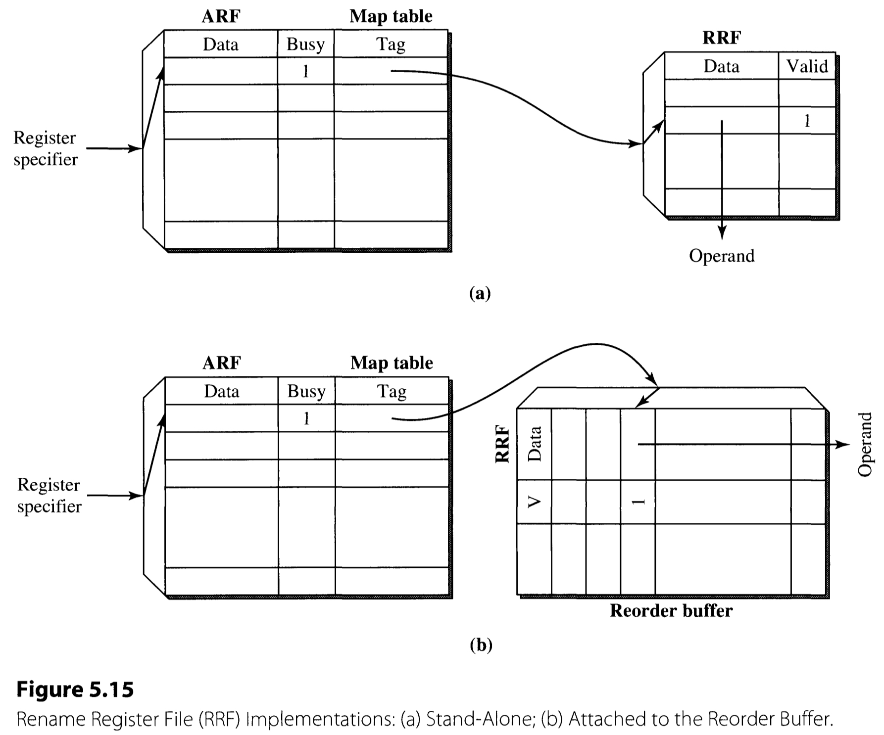
Figure 5.15 delineates the two common ways to implement the RRF. As in the figure, RRF can be implemented either (a) as a separate hardware or (b) attached to the reorder buffer. This chapter focuses on the design (a) to proceed to the details.
The register renaming consists of three stages:
-
Source read
The source read occurs at the decode stage. Once an instruction is decoded, the operands associated with it are fetched.
- If busy bit is not set, the data written in the ARF is read.
- If busy bit is set, this means that there is a pending write to that register.
- If the valid bit of the corresponding RRF entry is also set, this means the register-updating instruction has finished the execution, but is not completed. The data is fetched from the RRF entry.
- Otherwise, the state indicates that the register-updating instruction is still pending. This case, the tag(which specifies the rename register) is forwarded to the reservation station instead of the source operand, and is used to obtain the operand when it becomes available.
-
Destination allocation
Destination allocation also takes place at the decode stage, or possibly at the dispatch stage. The task comprises three subtasks: set busy bit, assign tag, and update map table.
- The busy bit of the destination register must be set, since there is a pending write to it.
- One of the unused entries of RRF is assigned and its index is used as a tag.
- The tag is written to the corresponding ARF entry’s map field.
- Register update
The register update is held in the back end of the machine. This is not actually a process that renames the register, but consists of updating first an entry in the RRF and then the corresponding entry of ARF.
The description above assumes that there are two separate physical register files, ARF and RRF. However, they can also be implemented together in a single physical register file which has the number of entries equal to the sum of two files. This pooled register file approach can be found in IBM RS/6000 implementation.
The implementation of register naming typically becomes more difficult as the pipeline width gets wider, as there may be multiple redefinition to the same register within a fetch group.
True Data Dependences and the Data Flow Limit
True dependences, i. e. Read-after-Write(RAW) dependences impose a real constraint to the data flow. To analyze the data flow, it is useful to plot it by a data dependence graph(DDG).
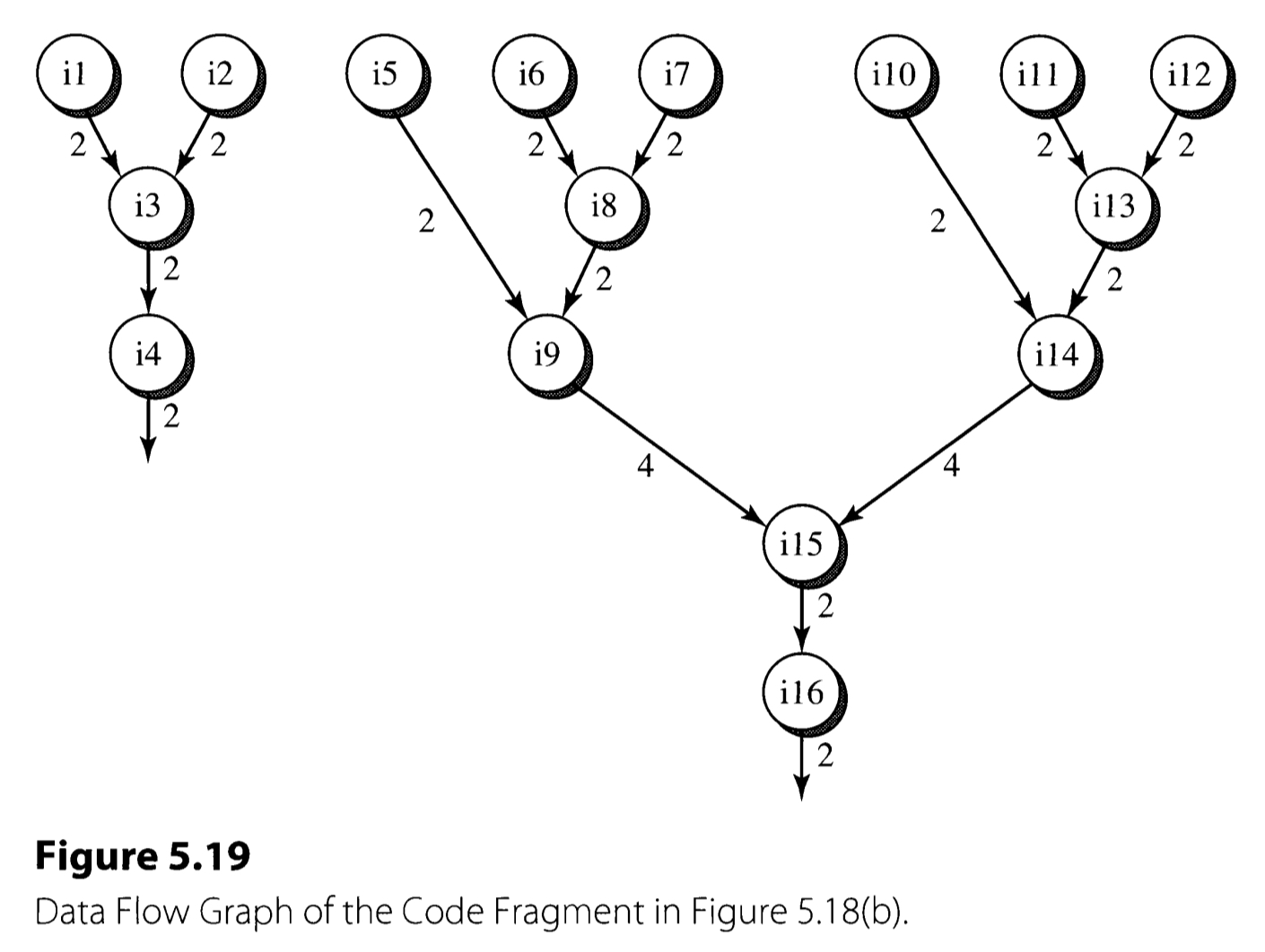
The critical path of the DDG in terms of the latency is the bottleneck of the execution performance, and often referred as the data flow limit. The data flow limit is dictated by the true dependences in the program. All the data flow techniques are the attempts to approach the data flow limit.
The Classic Tomasulo Algorithm
The Tomasulo algorithm is an algorithm that is used for dynamic scheduling the instructions efficiently. The book explains the algorithm by describing the floating-point unit employed in the IBM 360/91 processor.
The IBM 360/91 processor has three register files for storing floating-point data:
- FLR(Floating-point registers): architected, general-purpose floating-point registers.
- FLB(Floating-point buffers): buffer that stores the result of memory read.
- SDB(Storage data buffers): buffer that stores the information associated with memory write operation.
For example, when the floating-point operation takes the data in memory as an input, the FLB buffers the data in prior to the actual floating-point arithmetic. If the operation outputs to a memory location, the address and the value will be buffered in the SDB and the actual writing to the memory will be held at the commit point.

In the 360/91 design, three devices were newly introduced to implement the Tomasulo algorithm: reservation station, common data bus, and register tags.
- Reservation stations serve as waiting rooms for the instruction dispatched to each functional unit. By attaching the reservation station to each FUs, the processor can issue instructions even when the corresponding FU is still occupied, resulting in the reduction of unnecessary stalling. The instructions in the reservation station may be waiting for its input values to be available, or are just pending because the FU is occupied by the other instruction.
- Common Data Bus (CDB) performs all the interconnection required to implement the Tomasulo algorithm. It connect the outputs of functional units and the reservation station, FLR, SDB, and FLB. This helps forwarding the results of the instructions to other instructions in the reservation station that need the result. The bus always sends the payload value along with the tag, enabling each entity of the network latch the value only if the tag matches with what they are looking for.
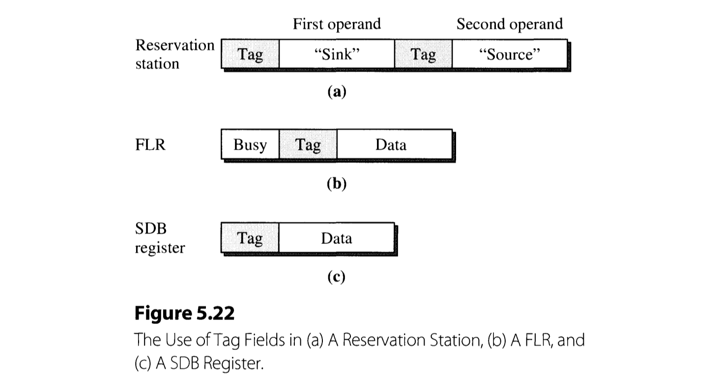
Figure 5.22 illustrates how the (register) tags are employed in reservation station, FLR, and SDB. When FLOS (Floating point operand stack) dispatches an instruction, it inspects if its operands are available or not. If an operand is available in FLR, the content of the register is directly copied to the reservation station. Otherwise, i. e. the operand is unavailable, being processed by the prior instructions, a tag corresponding to the operand is copied instead.
Example sequence of Tomasulo’s algorithm
Take the following instruction sequence for example. We assume that the addition and the multiplication have two and three cycles latency, respectively. Also, the machine is assumed to fetch two instructions per cycle.
w: R4 $\leftarrow$ R0 + R8
x: R2 $\leftarrow$ R0 * R4
y: R4 $\leftarrow$ R4 + R8
z: R8 $\leftarrow$ R4 * R2
Note that the actual IBM 360/91 has two-address format. Therefore, the notation sink and source just refers to each of the two operands here.
CYCLE 1: Instruction w and x are dispatched.

Each instruction is dispatched to the reservation station of adder and multiplier, respectively.
- Since w has all its operands ready, the operand values are directly loaded into the reservation station entry.
- Since source operand of x is not ready, its value is not loaded. Instead, the tag field is marked 1, indicating that it is waiting for the instruction in reservation station entry 1 (w) to finish.
- The busy bit of R2 and R4 are set, and the tags are assigned with the (latest) reservation station entry that has pending write to it.
CYCLE 2: Instruction y and z are dispatched.

y is dispatched to the adder reservation station, z to the multiplier.
- Since the sink of y and both the sink and source of z are not ready, their tags are loaded instead of values.
- The busy bits of FLR corresponding to the destination registers are set.
- The execution of instruction w(which has tag 1) is finished at the end of the cycle. Its result is broadcasted through CDB.
- The sink of y and source of x receives the value since they have the matching tag.
- However, data of R4 in FLR is not updated, and waits until the another pending instruction, y also finishes. Only its tag is updated to 2 as an indication for this.
CYCLE 3

- y and x begins execution in the adder and multiplier unit, respectively.
CYCLE 4

- Execution of y is completed at the end of the cycle.
- Sink of RS entry 5(z) and FLR entry R4 has the matching tag (2), and hence receives the result.
CYCLE 5

- Execution of x is completed at the end of the cycle.
- Sink of RS entry 5(z) and FLR entry R2 has the matching tag (4), and hence receives the result.
CYCLE 6

Instruction z begins its execution, and ends at cycle 8.
One of the features that is noteworthy is that FLR value of R4 is not updated at cycle 2, even though w: R4 $\leftarrow$ R0 + R8 is completed. Instead, CDB just broadcasts the result of w to the instructions that depends on the value of R4 (which reside in the reservation station). This is because another instruction y: R4 $\leftarrow$ R4 + R8 also has a pending write to R4. Through this mechanism, the processor can avoid write-after-write hazard (a.k.a. output dependence)
Dynamic Execution Core
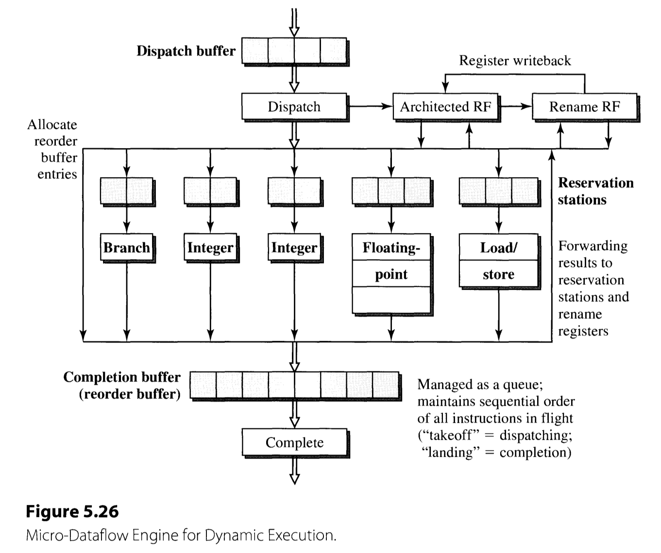
Most modern superscalar processors employs an out-of-order execution core(dynamic execution core) sandwiched between the in-order front-end and back-end. The dynamic execution core’s operation can be described in three phases: dispatching, execution, and completion. An outline of the processor’s behavior in each stage is described.
-
Instruction Dispatching
- Destination registers are renamed.
- An entry in the reservation station is allocated.
- The instruction is advanced from the dispatching buffer to the reservation station.
If any of these hardwares are unavailable, the dispatching is stalled.
-
Instruction Execution
- A ready instruction is issued (starts execution).
- An instruction in a reservation station entry is issued when all of its operands are available.
- The issued instruction is executed.
- Results are forwarded appropriately. This is done by the CDB with the destination tag.
Completion.
Typically, the reservation station entry is cleared once the instruction is issued. However, some instructions including those causing an exception may require its rescheduling. For example, a load instruction may trigger the D-cache miss. This case the instruction must be rescheduled for its re-execution after the cache loading. For these kinds of instructions, reservation station entry is not cleared at issuing.
Reservation Station and Reorder Buffer
The two critical hardwares of superscalar processor, excepting the functional units, is the reservation station and the reorder buffer. This section presents the issues regarding the two hardwares.
Reservation Station
There are three operations associated with the reservation station: dispatching, waiting, and issuing.
The dispatching is held in three stages:
- An empty reservation station entry is found. This is performed by the allocation unit.
- The operands and the tags are loaded.
- The reservation station entry’s busy bit is set.
Through these stages, an instruction in the dispatch buffer is associated with each of the functional units and loaded to an according reservation station.
An instruction with a pending operand is bound to wait in the reservation station. The pending operands can be latched when their tag matches with that broadcasted with the tag busses. When both of the operand fields are valid, the ready bit is set (instruction wake up).
The issuing step selects a ready instruction in the reservation station and issues it into the functional unit. Typically, the reservation station entry is deallocated in this step (with possible exception as described in the previous section).
Reorder Buffer
The reorder buffer stores all the in-flight instructions, i. e. instructions that are dispatched but not completed architecturally. Thus, all the instruction that are
- waiting in the reservation station,
- executing in the functional units, and
- finished execution but waiting to be completed in-order
are buffered. The buffer stores the status(waiting, executing, or finished) of each instruction, along with additional bits such as if the instruction is speculative or not. Only finished and nonspeculative instruction are completed. The implementation of the buffer is held as a circular queue, using an head and tail pointers.
Although the two hardwares, the reservation station and the reorder buffer, are usually implemented as separate hardwares, it is also possible to combine the two devices into a single structure called the instruction window.
Dynamic Instruction Scheduler
In the heart of the dynamic execution core is the dynamic instruction scheduler. The term includes the instruction window(i. e. the reservation station and the reorder buffer) and the wake-up and select logic.
The schedulers can be divided into two kinds, according to their design style: those with data capture and without data capture.
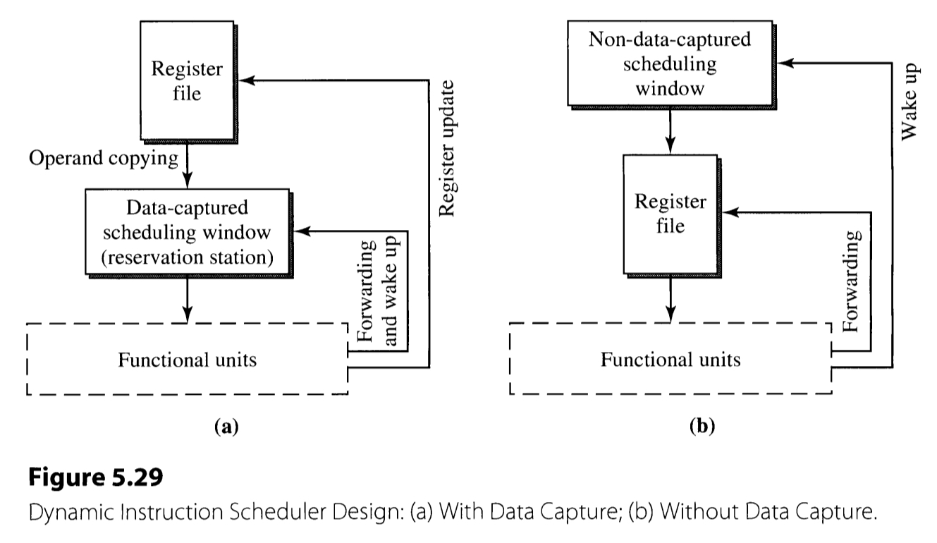
The former style of scheduler(Figure 5.29(a)) copies the instruction’s operands when dispatching. If they are not ready, the register tags are copied instead. When the functional unit finishes the execution, the result must be forwarded to the reservation station, as well as the original register file. This is the scheme used in the Tomasulo’s algorithm.
More recent processors often adopt the latter style of schedulers. This case, the register values are not copied to the scheduling window. The dispatching stage does not involve the actual copying of operands, and only copies the tags(pointers) to the operands. As a result, the forwarding and the wake-up path can be decoupled, and the separate register updating path becomes unnecessary.
The style of scheduler is closely related with the register renaming. In the data-capture schedulers, the register tags does not need to be the address of the actual physical register file, since it suffices for them to mark the producer-consumer relationship. The tags are not used to specify the actual register to write the result. However, in the non-data-capture schedulers, the execution results are written only to the physical register file according to the register tag. Therefore, there is no explicit register renaming.
Other Register Data Flow Techniques
The register data flow looks like if it is the ultimate limit of the performance. Nevertheless, back in the 1970s, the control flow dependency was also considered similarly. The conditional branches were thought to be the absolute impediment to the performance, necessitating stalls. However, as we know, this was broken by the development of branch prediction techniques.
The data flow limit can also be overcome by introducing value prediction technique. This utilizes the concept of value locality, which means that the values that appears frequently are likely to repeat in the future instruction results. If the results are predicted correctly during the fetch stage, the subsequent instructions can be executed without waiting for the instruction to produce the actual result.
3. Memory Data Flow Techniques
The last data flow dealt in this chapter is the memory data flow. The load and store operation to the main memory can sometimes be the bottleneck of the program performance. The issues related to data flow associated with the main memory are discussed.
Memory Accessing Instructions
The execution of memory instructions (load and store) are executed in three steps: address generation, address translation, and data accessing*.
The memory address generation is the step to generate the address of the memory that is accessed in the instruction. This stage is required since the memory address is not always specified in absolute manner, and may be in the forms demanding extra computations such as register indirect with offset.
The memory address translation incorporates the logic translating the virtual memory address into the physical address. This is usually implemented using the page table and the translation lookaside buffer(TLB), which stores the mapping between the virtual and the physical memory address. The TLB, which serves as a cache for the page table, is accessed primarily, and the page table is accessed in case of the TLB miss. If the mapping is also not resident in the page table, page fault occurs.
The final step, memory data accessing is the step that (apparently) accesses the actual memory. This step is processed differently in load and store instructions. In the load instructions, memory data is actually accessed. There may be possible stalling in case of D-cache miss. In contrast, writing instructions do not incorporate the actual memory accessing. This is because the writing to memory is irrecoverable if the instruction is cancelled due to possible exceptions or mispredictions. Instead, the store address and the data is temporarily stored in the store buffer, for architecturally completed stored instructions. The store results in the buffer is written to the main memory when the memory is idle, giving the priority to load instructions. The instruction can be called to have retired if it has updated the actual memory state. (In contrast, completed instruction refers to those that have changed the CPU state.) The store buffer is composed with finished portion and completed portion. The instructions that have finished address generation/translation reside in the former part, whereas those that are architecturally finished but waiting for memory update reside in the latter part.
Ordering of Memory Access
The data dependence may arise between the memory instructions, similar to the register dependences. Executing all the memory instructions in order may resolve the dependence, but this deteriorates the performance significantly. When executing the memory instructions out-of-order, there are two limitations imposed by the memory model:
- The sequence of memory state must be identical to that when the instruction sequence is processed in-order.
- If multiple processes access the shared memory, the accessing must be identical to the program order.
The two limitations require the store instructions to be executed in-order, or at least the memory to be updated in such way. This case, the WAW and WAR dependences are enforced implicitly, necessitating only the RAW dependence to be explicitly enforced. Now, load instructions can be processed out-of-order, if the instruction sequence obeys this constraint.
Load Bypassing and Load Forwarding
Now the goal of memory instruction scheduling becomes allowing the load instructions to be issued as early as possible, even if it requires the loads to jump ahead of preceding stores.
Load forwarding is employed in case of the preceding store and the load instruction share the same target address. This forwards the result of the store instruction and feeds it directly to the following load instruction. In contrary, if the target addresses differ, the load instruction can overtake the preceding store instruction. This is called the load bypassing.
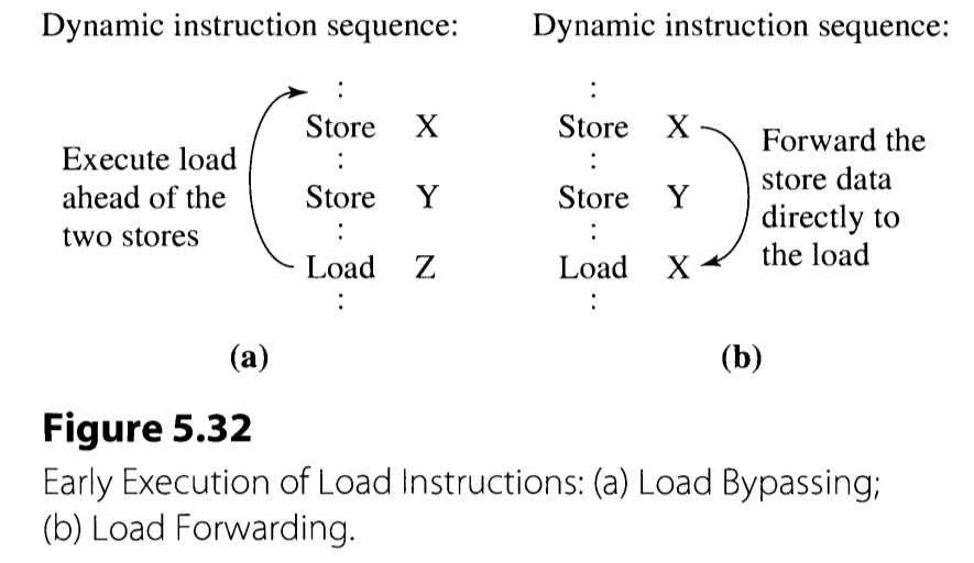
The load bypassing requires the alias checking to make sure its source does not match with the in-flight store operation. This process is quite straightforward, since all the in-flight store operations are present in the store buffer. The alias checking is performed in parallel with the memory accessing, to reduced the number of cycles. The memory access result is discarded if it turns out to have a memory aliasing. Otherwise, the load operation finishes and the corresponding register is updated. The alias checking can possibly be performed exploiting only a subset of the store address, although it may not be effective enough.
The load forwarding performs the associative search of tag in the similar manner with load bypassing. The technique forwards the store value to the renamed register if there occurs a tag match. The load forwarding requires even more hardware that the load bypassing, since:
- The aliasing detection using only the subset of the address would not work and cause semantic incorrectness.
- The logic must detect the latest store operation if there are multiple in-flight stores.
- This requires not only the D-cache, but also the load unit to possess an access to store buffer read port.
So far we have discusses only the case of in-order issuing of load/store reservation stations. The advantage of in-order issuing is that the load instruction can inspect only the store buffer to alias-check all the in-flight store instructions. However, out-of-order issuing is often considered to alleviate the bottleneck arise from cases where store instructions block the subsequent load instructions.
In case of out-of-order issuing, the preceding stores may not have completed when a load is issued. Therefore, the issuing is speculatively performed, assuming there is no alias and the assumption is verified later. The finished load is stored in a new buffer called the finished load buffer, a la the finished store buffer. In order to reduce the miss penalty here, the logic predicting whether there is aliasing or not can be introduced (dependence prediction).